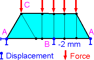
 Application of boundary conditions is the most critical stage of the finite element analysis.
To simulate the constraints imposed on the physical motion of the structure, displacement boundary conditions A, B must be defined. Prescribed displacements can have zero A or non-zero B values. There are also load boundary conditions, C.
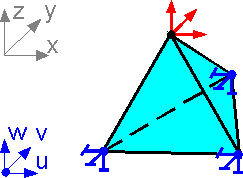 The boundary conditions (fixation or force for a direction) are applied at the nodes only. Maximum number of boundary conditions for a node is equal to the degrees of freedom: 3 restraints or forces for a node in this example.
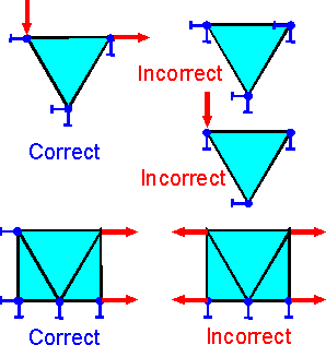 Great care must be taken so that the finite element model is neither under constrained nor over-constrained.
It is not possible to fix all degrees of freedom (all nodal displacements) for an element. It is better to remove the element from the model.
It is not possible to fix a node and to apply force in the same direction.
Absence of restraints along an axis can lead to a shift along the axis due to errors in numerical calculations. The correct boundary conditions must have at least one restraint for each axis.
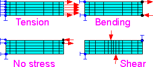 Different sets of load and displacement boundary conditions can be implemented to represent model tension, pure bending or shear.
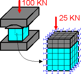 There are three planes of symmetry in this example. If the cube is more flexible than the platens then there is no need to model the entire structure. All points of the upper cube surface will have virtually the same vertical displacements.
St Venants principle:
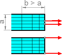
Two sets of statically equivalent forces produce the same stress field at distance that is large compared to linear dimensions of cross section: b > a.
This principle is often utilized to replace complex boundary conditions with statically equivalent loads.
The figure shows two equivalent loading schemes.
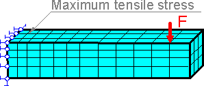 Tensile stresses are frequently the reason for failure in a structure. If the region of maximum tensile stress extends beyond the region of the applied force it is not necessary to have a very fine mesh in that region. There are compressive stresses in region of applied force.
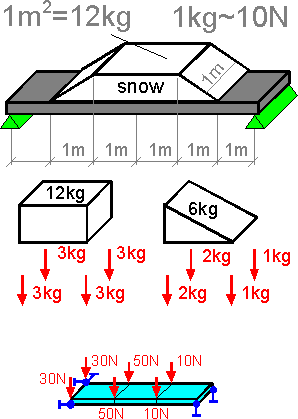 This is an example how the distributed load are spread over the nodes. The sum of the force is equal to 18 kg for a half of the plate. The force can be distributed as the weight over 6 nodes.
 2015-08-13
 471
471


