2015-08-21
 503
503| Bolt diameter | M10 | M12 | M16 | M20 | M24 | M30 | M36 |
| Hole diameters for anchor bolts | - | ||||||
| Hole diameter for tie bolts | - |
12.3. Designing casings.
Casings are used to support torque-transmitted elements in design position and take up loads developed in speed reducers during operation. The main material of casings is cast-iron.
A casing must be rigid to prevent shaft misalignment under internal and external loads. This can be achieved by using stiffening ribs that also carry out the function of cooling fins.
Casing may have split or single-peace construction. For split constructions the joint between a casing and a cover is usually provided in the plane parallel to the base and that passes through the axis of rotation of corresponding gears.
The main dimensions of the casing (Fig. 12.7):
12.3.1. Casing and cover wall thickness:
- for single stage spur gear speed reducer d = 0.025· a +1 ³ 8 mm;
- for single stage bevel gear speed reducer d = 0.05· Re +1 ³ 8 mm;
- for single stage worm gear speed reducer d = 0.04· a + 4 ³ 8 mm;
- for double stage gear speed reducer d = 0.025· aL +3 ³ 8 mm,
where a is the centre distance, aL is the center distance of the low-speed transmission, Re is outer cone distance.
12.3.2. Flange thickness at the joint plane
b = 1.5·d.
12.3.3. Thickness of the flange for connection to a frame
p = 2.35·d.
12.3.4. Thickness of the rib
m = (0.8…1.0)·d.
12.3.5. Diameter of the anchor bolt
d 1 = (0.03…0.036)· aL +12,
d 1 = 0.072· Re +12.
Obtained magnitude of d 1 should be rounded off to the nearest greater side according to standard series given in table 12.9.
12.3.6. Number of anchor bolts
z = 0.005·(L 0+ B 0) ³ 4,
where B 0 is the width of the speed reducer base; L 0 is the length of the speed reducer base. It is necessary to note that the number of anchor bolts should be always even.
12.3.7. Diameter of the tie-bolt near bearings
d 2 = (0.7…0.75)· d 1.
Obtained value of d 2 should correspond to standard value (table 12.9).
12.3.8. Diameter of tie bolts that connect the casing and the cover flanges
d 3 = (0.5…0.6)· d 1.
Round off obtained value of d 3 to the greater side according to standard series (table 12.9).
12.3.9. Distance between tie-bolts of diameter d 3
l = (10…12)· d 3.
12.3.10. Disposition of bolts on the flange (Fig)
x = (1…1.2)· d hole,
y = d + e,
where d hole is the diameter of the hole for fitting the bolt (table 12.7);
e is the distance that allows to grip the bolt head by a spanner (table12.8).
Table 12.8
Value of e
| Diameter of the bolt | M10 | M12 | M16 | M20 | M24 |
| e, mm |
12.3.11. Height of the boss is determined from structural consideration taking into account the following requirement
q ³ 0.5· d 2 + dk,
where dk is the diameter of the bolt, that connects the bearing cap with the casing (table12.4).
 | |||
 |
12.3.12. Dimensions of bolts, nuts and washers are given in tables 12.9 -12.11. The length and threaded length of the bolt are given in table 12.12. Engaged length of the bolt, the depth of the hole and threaded length of the hole are determined according to table 12.13.
12.3.13. In order to hold together the casing and the cover and to prevent their relative movement in axial direction two pins are used. They are placed along the flange diagonal. The diameter of the pin is determined as d pin = 0.5· d 1.
12.3.14. For transition and installation the cover and the casing should be made with lifting eye-bolts (table 12.14) or eyes and load hooks (Fig. 12.8).
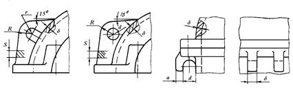
r = 1.5·δ; R = 3·δ; d = 3·δ; a = (1.2…1.5)·δ; s = (2…3)·δ
Fig.12.8. Load eyes and hooks
12.3.15. For gear inspection and lubrication an inspection hole is provided in the upper portion of the cover. The cover of the inspection hole is determined according to table 12.15.
12.3.16. During operation, pressure inside a casing increases due to heating of the oil and air. As a result the lubricant is ejected outside through seals and joints. To avoid this fact air-vents are provided in the top portion of the casing for communication between the inner space and the environment. Possible constructions of air-vents are given in tables 12.16 and 12.17.
12.3.17. For draining the oil with grit and other debris a drain hole is made in the casing bottom, which is stopped with a plug with either straight or taper thread (table 12.18).
12.3.18. The level of the oil contained in the speed-reducer casing is checked with oil gauges of various constructions. Among them there are dip sticks (table 12.19) or transparent tube gauges. (table 12.20).
Table 12.9
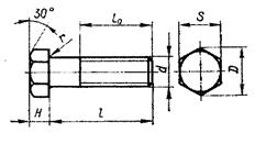 |
Standard bolts (GOST 7798-70)
| Parameter | Thread diameter d, mm | ||||||
| Thread pitch, mm | 1.0 | 1.25 | 1.5 | 1.75 | 2.0 | 2.5 | 3.0 |
| Radius r, mm not more | 0.6 | 1.1 | 1.1 | 1.6 | 1.6 | 2.2 | 2.2 |
| Diameter D, mm | 14.5 | 33.5 | 40.5 | ||||
| Span S, mm | |||||||
| Height H, mm | 4.5 | 5.5 |
Table 12.10