2015-08-21
 468
468| Oil | Oil grade | Kinematic viscosity, 10-6м2/с |
| Industrial at 50°С | И-12A | 10-14 |
| И-20A | 17-23 | |
| И-25A | 24-27 | |
| И-30А | 28-33 | |
| И-40A | 35-45 | |
| И-50A | 47-55 | |
| И-70A | 65-75 | |
| И-100A | 90-118 | |
| Aviation at 100°C | МС-14 | |
| МК-22 | ||
| МС-20 | 20.5 |
Immersion lubrication is effective when peripheral speed is less than 10 m/sec.
The oil bath lubricates the larger wheel. The recommended depth of immersion of high-speed spur gear is ranged form m to 5· m but not less than 10 mm (m is the module of the gearing). Low-speed spur gear should be immersed not more than 100 mm. Bevel gears are immersed along the entire length of a tooth.
If toothed wheels cannot be lubricated by immersing the additional pinions, rings or other devices are used (Fig. 12.9).
In worm-down speed reducers the oil level should not exceed the thread height of the worm. But in this case the oil level should not rise above the centre of the lower rolling element of the worm shaft bearings. If the worm is not immersed in oil the additional rings with blades are used (Fig. 12.10)). In worm-up arrangement the worm gear should be immersed not more than 1/3 of the worm gear radius.
Let us determine the volume of the oil bath.
Needed volume is chosen to ensure removing the heat generated in the engagement of a gearing to casing walls. Recommended volume of the oil bath is chosen as 0.6 to 0.8 liter of the oil per 1 kilowatt of transmitted power. Consequently, the needed volume V = (0.6…0.8)· P motor.
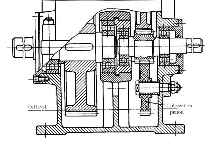 Fig. 12.9. Lubrication pinion made of textolite

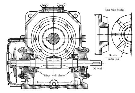
Fig. 12.10. Ring with blades
The larger volume, the longer oil life and better lubrication conditions. That is why the volume of the oil bath is only limited by the maximum permissible oil level in the casing.
The distance between the oil level and the speed reducer bottom is determined as  , where S = L×B is the area of the speed reducer inner space in dm2; L and B are correspondingly the length and the width of the speed reducer inner space in dm. It is necessary to note that the minimum distance between tops of teeth of the larger gear and the speed reducer bottom is 20 mm.
Lubrication of bearings.
Bearings may be lubricated with the same oil as used for the mashing parts (when the peripheral speed is greater than 3 m/sec) or individually with greases.
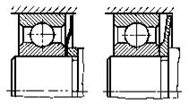
| Fig. 12.11. Bearings with shields |
 Splash lubrication is used when the bearings are installed in cases which are not insulated from the general system of lubrication unit. Rotating parts (gears, wheels etc.) come into contact with oil which is fill in into the housing then under rotation sprays oil, which falls on the rolling bodies and bearing tracks.
To protect the bearings from the heavy jets of oil (which create high-speed helical pinions or worms) and getting into them products of wear the shields (protective washers) are installed (Fig. 12.11).
Pressure lubrication through nozzles is used for reducers, working long time without interruption, as well as for the bearings of high-speed transmission, which is necessary to provide intensive heat removal.
Oil fog lubrication is used for high-speed understressed bearings. With help of special nozzles under pressure in the unit supplied a jet of air, which carries oil particles.
This method allows to penetrate the oil in the bearings, located in inaccessible places, creates a flow with minimal lubrication oil consumption provides a good cooling of bearings and the pressure protects the assembly from contamination.
| Fig. 12.12. Grease-retaining ring |
| Fig. 12.13. Bearing assembly with grease cup |
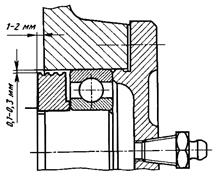
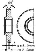 Greases offer better protection against corrosion than oils and it's used when environment contains harmful impurities or the temperature of the assembly sharply changes. In this case grease-retaining rings (Fig 12.12) are used to isolate the bearing cavity from the inner space of the casing. The ring periphery should extend over the end face of the bearing housing for 1 or 2 mm (Fig. 12.13). The gap between the ring periphery and the housing should be about 0.2 mm. The ring rotates together with the shafts and it has from two to four grooves. In order to feed the grease inside the bearing without removing the cap grease cups are used (Fig.12.13). The lubricant is injected under pressure by means of a grease gun.
12.5. Analysis of keyed joints.
Dimensions of keys are chosen according to table 12.24 depending upon the shaft diameter. The length of the key should be less than the hub length by 5…10 mm and correspond to the standard series.
In general-purpose speed reducer, keyed joints are usually analyzed to prevent bearing stresses.
 ,
,
where T is the torque in N∙mm; d is the diameter of the shaft in mm; h is the height of the key in mm; t 1 is the depth of the slot in the shaft; ld is the design length of the key in mm (for keys with round sides ld = l – b; for keys with square sides ld = l, where l is the length of the key; b is the width of the key); [σ bear ] is the allowable bearing stress (for cast-iron hubs [σ bear ]=60…80 MPa; for steel hubs [σ bear ]=100…120 MPa).
Table 12.24