2015-08-21
 335
335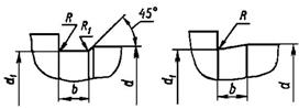
| d | b | d 1 | R | R 1 |
| Over 10 to 50 | d – 0.5 | 0.1 | 0.5 | |
| Over 50 to 100 | d – 0.5 | 1.6 | 0.5 | |
| Over 100 | d – 1.0 | 2.0 | 1.0 |
The next step is dimensioning the drawing. The number of dimensions should be minimal but enough to produce the shaft. Chamfers and grooves width cannot be included to the total dimensions chain.
There exist three methods of dimensioning drawings:
- chain method that provides the accuracy of disposition of every following element relative to the previous. In this case the accuracy relative to certain base is decreased;
- coordinate method according to which dimensioning of a drawing is carried out with respect to base A;
- combined method that consists of the chain and coordinate methods.
For the shop drawing the recommended method is combined method. Dimensioning in the axial direction is carried out under an element drawing.
As it is known dimension must be held between two limits. The difference of these limits is called tolerance. Tolerance limits of relatively low accuracy dimensions are not marked on a drawing. In this case it is necessary to make the following inscription:
“ Dimensional tolerances: holes H14, shafts h14, other elements  (medium accuracy class) ”.
The nature of elements connections is called a fit. Fits may provide clearance or interference. There exists also transition fits that may have either clearance or interference. Fits are marked by a letter of Roman alphabet. Letters a-h corresponds to clearances, js-n – transition fits, p-z - interference. A numeral near a letter shows the quality grade. There exist 19 quality grades. For mechanical engineering the most typical are quality grades 5 through 12. Quality grades 6 through 8 refer to critical parts and units.
Example of the shaft drawing – Fig. 14.1, example of the gear construction – Fig. 14.2.