2015-08-13
 590
590In a preliminary calculation suppose usually, that the cooling surface of direct-current coil Scol are external Sex and internal Sin its surface and ignore cooling of butt ends. Equality (fig. 1.1) is thus just:
Sex = π∙ Dex∙H = π∙ m ∙(1 + 2 n)∙ d 2 c, (1.5, a)
Sin = π ∙Din∙H = π ∙m∙d 2 c, (1.5, b)
where Dex = dс + 2 А; Din ≈ dc, and accordingly height of Н and width A winding of coil is expressed through a qualificatory size dc and dimensionless coefficients of proportion of m and n, i.е.
Н = m∙dс, A = n∙dс. (1.6)
In accordance with equation of coil heating in the continuous running duty we have:
Θ per = R∙I 2 / [ h∙ (Sex + α∙Sin)], (1.7)
where h − coefficient of heat emission from the surface of coil, W /0∙ cm 2; its value can be chosen for the exceeding of temperature Θ per under formula:
h = 9,3∙10-4 ( 1 + 0,0059∙Θ per
α − coefficient, taking into account influence of windung method of coil on its heat emission: self-supported, shrouded, winded on a pipe, winded on a core or wireframe coil (hin = α∙h − coefficient of heat emission from the internal surface of coil, α = 0,9 − for the self-supported shrouded coil; α = 1,7 − for a coil, winded on a pipe; α = 2,7 − for a spool, winded on a core; α = 0 − for coils, having isolating framework of material, badly conducting warm, and coils of alternating current).
I − current, flowing in a coil, a; R − resistance of coil, refered toϑ per = Θ per + 350 С.
As is generally known,
R = 10-4ρ∙ w∙lav / Sm = 10-4ρ∙π∙ Dav∙w / Sm = ρ∙π∙(1 + n) dc∙w / (104∙ Sm) (1-8)
where ρ − specific resistance of wire metal of coil at ϑ per, Ω∙ mm 2/ m. Specific resistance ρ of wire material it is necessary to refer to the permissible temperature of coil: ϑ per = Θ per + ϑ env, here ρ = ρ0(1 + α0∙ϑ per), where ρ0 is specific resistance at 00С; α0 is a temperature coefficient of wire metal. For a copper wire α0 = 0,00393 within the limits of heating of 10÷1000С, ρ0 = 0,0162. For a leader copper a value ρ for most often meeting working temperatures is driven to the table.2:
Table. 2
| ϑ per (0С) | ρ (Ω mm 2/ m | ϑ per (0С) | ρ (Ω mm 2/ m | ϑ per (0С) | ρ (Ω mm 2/ m |
| 0,01754 | 0,02170 | 0,02339 | |||
| 0,01857 | 0,02236 | 0,02370 | |||
| 0,01991 | 0,02300 | 0,02443 |
lav, Dav − length and diameter of middle loop of coil, cm;
Sm – cross-section of wire metal of coil, см 2;
w − number of coil loops.
On determination of aperture occupation ratio of winding we will get:
fap = Sm∙w / HA = Sm∙w / m∙n∙dc 2,(1.9)
from where we find the cross-section of wire metal
Sm = fap∙m∙n∙dc2 / w (1.10)
Putting (1.10) in (1.8), and then (1.5) and (1.8) in (1.7), we will define:
Θ per = ρ(1 + n)∙ w 2 I 2 / [104∙ fap ∙ m 2∙ n∙h∙ (1 + 2 n + α)∙ dc 3]
From here it is easily to define necessary coils MMF:
w∙I = √ [104∙ fap ∙ m 2∙ n∙ (1 + 2 n + α)∙ h∙ Θ per ∙ dc 3] / ρ(1 + n) (1.11)
Putting a value w∙I from (1.11) in (1.4), we find a basic formula, defined force of electromagnet:
F 0 = [4∙104 ∙μ 0 ∙ φ2∙ε2∙χ2 ∙ fap∙ τ2 ∙m 2 ∙n∙ (1 + 2 n + α)∙ h∙ Θ per ∙ dc 5] / [ρ(1 + n) δ02] (1.12)
From the last formula we find the key size of electromagnet:
dc = 5 √ [2∙103∙ ρ(1 + n)∙ F 0∙ δ02] / [φ2∙ε2∙χ2 ∙ fap∙ τ2 ∙m 2 ∙n∙ (1 + 2 n + α)∙ h∙ Θ per ] (1.13)
Entering denotation
C 1 = [2∙103∙ρ(1+ n)] / [φ2∙χ2 ∙fap∙ τ2 ∙m 2 ∙n∙ (1+2 n +α)∙ h∙ Θ per ],(1.14)
we will rewrite formulas (1.12) and (1.13) so:
F 0 = ε2 ∙dc 5(1.15)
and dc = 5 √ [ C 1∙ F 0∙ δ02 / ε2], (1.16)
where F 0 − force, kg, and δ0 – air gap, cm − are set by the critical terms of design;
ε eq, ε − are dimensionless coefficients, taking into account buckling of flux and define equivalent conductivity of basic gap or her derivative ε = ε (δ0, dc), ε eq = ε∙δ0, dc;
С 1− constant, determined by factors, included in a formula (1.14), namely: ρ, fap − constants, determined by the type of the chosen wire and method of its winding;
Θ per, h, α − constants, determined by the terms of the permissible heating;
m, n, τ, φ − constants, determined by the optimally chosen sizes of coil and magnetic core;
2 ∙103 − constant, determined by chosen system of units.
About the practically recommended values of indicated constants, determined the task solution, approaching optimal terms, it will be rendered below. Possibility of close estimation of buckling coefficient ε, which in case of basic gap, formed by a cylindrical core and flat armature, can be expressed by next dependence: ε2 = 1 + [2,08 / (τ∙ dc / δ0)].
A value ε for most electromagnets of the examined form is within the limits of 1 ÷ 1,6, however depends considerably on sizes δ0 and dp = τ∙ dc.
Thus, the coefficient ε or ε eq included in a formula (1.16) is the function of gap δ0 and diameter dc, that complicates the determination of key size dc from this equality.
Therefore for the calculation of dc next methodology can be recommended:
 We will transform a formula (1.16) so:
F 0 / δ03 = (1/ С 1)(dc/ δ0)5∙ε2, или F 0 / δ03 = χ5∙ε2 / С 1, (1.17)
where χ = dc / δ0 (1.18)
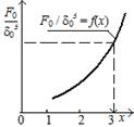
In the interval of the supposed change of δ0 / dс, or χ = dc / δ0, for example 0,1 ≤ (δ0 / dс) < 1 or 1< χ ≤ 10, at constant value С 1 and τ; set by Fig. 1.2 values χ = 1, 2, 3.., it is easily to define by a formula (1.17) a value F 0 / δ03 and, thus, to build the curve of functional dependence of F 0 / δ03 = f (fig. 1.2 and table. 3).
Then at the reverse raising of task, i. е. at a set value F 0 and δ0, determine the size of F 0 / δ03 and, using the got curve, find the relation χ = dc /δ0 and, so, for set value of δ0 the sought value dc.
At the change of values С 1 and τ a family of analogical curves can be got.
By found value of key size dс it is easily to find the cross-section of wire metal Sm and number of coil loops w.
Really, because on (1.8)
R = 10-4∙ρ∙π∙(1 + n)∙ dc∙w / Sm,, then w∙I = w∙U/R = 104∙ U∙Sm / [π∙ρ∙(1 + n)∙ dc ], from where Sm = [ρ∙π∙(1 + n)∙ dc∙w∙I ] / 104∙ U.
Table. 3
| x | x 2 | x 3 | x5 | ε 2 ε eq 2 | x 5ε2 x 5εeq2 | F 0 / δ03 |
On the other hand, MMF of coil by (1.11) with a glance (1.14) can be expressed so: w∙I = (4,5∙103 / φ∙χ∙τ)∙ dc∙√ (dc/C 1)
So, the cross-section of wire is determined by formula
Sm = 1,41∙ρ∙(1 + n)∙ dc 2∙ √ (dc/C 1 / (φ∙χ∙τ∙ U), [ сm 2], (1.20)
and number of coil loops − by a formula:
w = fap∙HA / Sm = φ∙χ∙τ∙ U∙fap∙m∙n ∙√(C 1/ dc) / [1,41∙ρ∙(1 + n)] or
w = C 2 ∙U∙ √ (C 1/ dc) (1.21)
where it is accepted: C 2 = φ∙χ∙τ∙ fap∙m∙n / [1,41∙ρ∙(1+ n)] (1.22)
On occasion it is comfortably to use dependence:
w = U ∙√{103∙ fap∙n / [ρ(1+ n)(1+2 n +α)∙ h ∙Θ per∙dc ]}
The formulas got higher upon calculation of key size of electromagnet and winding data of coil are correct in the wide range of induction, however at its values, exceeded a limit, corresponding to steel saturation, the got dependences lost a fisical sense.
In accordance with it at the calculation of electromagnet core it is necessary to specify the value of induction, which a key size dс is got at.
A value of induction in steel, and so, its less value in a working air-gap, can be defined by the values of dс, ε and given initial terms of design (F 0 and δ0), found in a preliminary calculation from a formula (1.1):
B 0 = 0,56∙10-4∙√ F 0 / τ∙ε∙ dc.
As specified, this value is specified in the subsequent project calculation of induction and under existent experience of design and production of electromagnets must not excel the values of order
(0,6÷0,8)∙10-4, Wb / cm 2.
For the exception of the repeated calculations the value of induction in a basic working gap can be got approximately, before the calculation of key size of core, by formula:
B 0 ≈ 4,8∙10-5∙[10√(F 03 / δ04)] / τ∙(5√ C 1)
Nonconformance of the got value of induction with permissible indicates about unsuccessful choice of factors of preliminary calculation or accepted type of electromagnet for the set terms of its operation, required force and motion of armature.
Change of the got value of induction, as be obvious from the formula given above, at maintenance of the set terms of design (F 0 and δ0) can be made due to clarification of coefficients of preliminary calculation in the real limits of their change.
So, for example, at the chosen value of п only due to the change of relation of coil height to the width of its window β = m / n
in limits from 1 to 10, it is possible to change induction В 0 in 1÷2,5 time. A value of induction can be corrected due to clarification and other coefficients of preliminary calculation (τ, n, Θ per and other).
In electromagnets with small critical air-gaps and insignificant leakage flux the induction in a gap can some exceed the legitimate values indicated higher.
In some designs of electromagnets, at which the initial terms of planning require creation of small critical forces and relatively large critical air-gaps, for maintenance real structural ratio and optimal terms on heating the induction in a air-gap it is needed to take considerably below than recommended.
In electromagnets with considerable critical forces and small air-gaps at maintenance of desirable design correlations and legitimate values of induction it is necessary agree to incomplete use of coil by heating.
b) Recursive short-time mode
Operation of electromagnet in the recursive short-time modeis determined by the alternate swithing on of its coil on a turn-on time ton and subsequent after this shutoff on a time of pause t p.
As it is generally known, such mode is characterized by relative duty ratio (DR %, which is ratio in percent of ton toward duration of cycle tcl = ton + tp.
DR % = (ton / tcl)∙100
It is thus assumed that during switching-on a current I = const flows through a coil, in a shutoff period − I = 0.
Thus, at determination of electromagnetic force, created by an electromagnet during turn-on time it is necessary to include a full rated value of MMF w∙I in a calculation of force, and so, induction.
Thermal calculation of coil at this mode it is possible to make coming from assumption, that coil is heated by the equivalent warming current Iht < I, flowing through it long time, i.е.
Θ per = R∙I 2 ht / h∙Scl
As it is generally known, Iht is determined by a formula: I / Iht = pcr, where рсr – overload factor by current, equal for the recursive short-time mode:
рсr = √[(1− e-ton/T) / (1 – e-tcl/T)],
where Т − time constant of coil heating, s; е − natural logarithmic base.
If time of cycle tcl is considerably less time constant of coil heating Т, that is correct for most electric devices coils (ton << T), then a factor рcr can be expressed so:
рcr = √ (100/ DR%)(1.23)
Simple transformations, similar to used for the continuous running duty, enable to define a full MMF of coils for a recursive short-time mode:
w∙I = рcr √[104∙ fap∙m 2 ∙n∙ (1 + 2 n + α)∙ h∙ Θ per ∙ dc 3/ρ(1 + n)] (1.24)
Thus, at the recursive short-time flowing of current I in the coil a permissible by heating MMF can be increased in рcr time as compared to the recursive short-time.
Necessary for creation of force F 0 an induction В 0 is determined, as well as before, by (1.3):
В 0 = χ∙μ0∙φ∙(wI) / δ0 = [χ∙μ0∙φ∙ рcr / δ0]∙√ [104∙ fap∙m 2 ∙n∙ (1 + 2 n + α)∙ h∙ Θ per ∙ dc 3/ρ(1 + n)] (1.24)
and, so, a key size of electromagnet core is defined in this case by a formula
dс = 5 √ (C 1 F 0 ∙ δ20 / р 2 cr∙ε 2) (1.25) From comparison of (1.16) and (1.25) it is clear, that if the current I flows through a coil in the recursive short-time duty, then the electromagnet core can be chosen with the diminished size in 1/ рcr 2/5 times as compared to the sizes of electromagnet of the same type, operating in the continuous running duty at the same current in a coil.
For electromagnets, operating in the recursive short-time duty, like formulas (1.19), (1.20) and (1.21) it is possible to get:
MMF of coils:
w∙I = (4,5∙103∙ рcr∙dc / φ∙χ∙τ) ∙ √ dc/C 1 (1.26)
2) Cross-section of wire:
Sm = [1,41∙ρ∙(1 + n)∙ рcr∙d 2 c / φ∙χ∙τ∙ U ]∙ √ dc/C 1 (1.27)
number of coil loops:
w = (U/ рcr)∙√[103∙ fap∙n / ρ∙(1 + n)∙(1 + 2 n + α)∙ h∙ Θ per ∙ dc ] or
w = [φ∙χ∙τ∙ fap∙n∙m∙U /1.41∙ρ∙(1+ n)∙ рcr ]∙√(C 1/ dc) = C 2 ∙U/ рcr ∙√(C 1 /dc)
c) Short-time duty
At this mode the electromagnet coil can endure considerably a greater current load, than at continuous running duty. It enables to decrease its sizes, and so, key size of electromagnet core.
At determination in the preliminary calculation of coil heating, switched on during the small interval of time (turn-on time ton), about a few
seconds, it is possible to consider that all heat, radiated in a coil, is expended on heating of its active material (for example, copper), i.е. to ignore heat emission in an external environment and heating of insulants, included in its construction.
Equation of coil heating in this case will be:
R∙I 2∙ ton = с∙G ∙ Θ per, (1.29)
where c − specific heat capacity of active material of wire, J / g ∙0 C;
G − weight of active material of wire, g;
I − current of this short-time duty, A.
Weight of active wire material can be determined in such way:
where γ m is a specific gravity, g / сm 3; lav is a length of middle loop of coil, cm; Sm – cross-section of wire metal, сm 2; w − number of coil loops.
Substitution of value G from (1.30) and R from (1.8) in equation (1.29) gives: (I / Sm)2 = 104∙ c∙γm∙ Θ per / ρ∙ ton.
A current density j, [ A / cm 2] in the coil section equals to:
j = I / Sm = √ [104∙ c ∙ γm∙ Θ per / ρ∙ ton ](1.31)
At load duration in one second (ton = 1 s, onesecond current), a current density is determined by a formula:
j = √[ c ∙γ m ∙Θ per / 10-4ρ] and, so, j = j 1 / √ ton.
For coils of a copper wire, if to accept: γ m = 8,9 g / сm 3, c = 0,39 J / g∙ 0 C, the permissible current density at the onesecond load practically can be accepted in accordance to a table. 1.2, where the values of temperatures ϑ m.per and corresponding to it values of j 1 are brought accepted by ГОСТ.
Table 4
| Class of isolation | Y | A | Compounded coils |
| ϑ m.per (0 C) | |||
| Θ m.per = ϑ per − 35 (0 C) | |||
| j 1 (A / сm 2) | 10∙103 | 10,8∙103 | 11,7∙103 |
As follows from a table. 4, at a preliminary calculation it is possible on the average to accept j 1 = 11000 A / сm 2 = 110 A / mm 2, or with some reserve on heating j 1 = 100 A / mm 2: j = 104 / √ton.
On the other hand, because by a formula (1.10)
Sm = fap∙m∙n∙dc 2 / w, then j = I / Sm = w∙I / fap∙n∙m∙dc 2, from where
w∙I = j∙ fap∙n∙m∙dc 2 (1.33) and, so, by (1.3)
В 0 = χ∙μ0∙φ∙(wI) / δ0 = χ∙μ0∙φ∙ j∙fap∙n∙m∙dc 2 / δ0 (1.34)
Substituted a value S 0 (1.2) and В 0 (1.34), we will define the size of electromagnetic force by (1.1):
F 0 = 4∙ χ2∙μ0∙φ2∙ j 2∙ fap 2 ∙n 2 ∙m 2 ∙dc 6∙ε2∙τ2 / δ02 (1.35)
from where with a glance of (1.31) it is possible to find a key size of electromagnet core for short-time duty with the set turn-on time:
dc = 6√[2∙103∙ρ∙ ton ∙δ02∙ F 0 / (χ2∙φ2∙ c∙γm∙fap 2∙ n 2 ∙m 2 ∙ ε2∙τ2∙Θper)] or, if to take on a close value of j = 104 / √ton,
dc = 6√[0,2∙ ton ∙δ02∙ F 0 / (χ2∙φ2∙ fap 2∙ n 2 ∙m 2 ∙ ε2∙τ2)] (1.36)
In general case we have:
dc = 3√[(C 3 ∙ δ0/ε)√ F 0∙ ton ] (1.37)
where C 3 = √[2∙103∙ρ / χ2∙φ2∙ c∙γm∙fap 2∙ n 2 ∙m 2∙τ2∙Θper] = √{[ C 1∙ h∙ (1 + 2 n + α) / [ n ∙(1 + n)∙ fap∙c∙γm ]} (1.38)
at the close value of j = 104 / √ ton
С 3 = 0,14/ (χ∙φ∙ fap ∙ n∙m ∙τ) (1.38, а)
Because ε, in turn, depends on dс, then, as well as before, for determination of dс can be recommended the following methodology.
We will transform a formula (1.37) so: (d с / δ0)2 = С 3∙(√ F 0∙ ton) / (δ02∙ε). From here
(√ F 0) / δ02 = χ3∙ε / (С 3√ ton) (1-39)
Set by values χ, it is possible to define (√ F 0) / δ02 and then, as well as before, to build graphic dependence (√ F 0) / δ02 in a function of χ.
At solution of reverse task by the known values of F 0 and δ02 determine (√ F 0) / δ02 and find χ = dс / δ0 by a chart. By value χ and given δ0 find the key size of electromagnet core dc = χ∙δ0,
and so, coil sizes and cross-section of wire metal:
Sm = π∙ρ∙(1 + n)∙ j∙fap∙n∙m ∙ dc 3 / 104∙ U, (1 -40)
or at the close value of j = 104 / √ ton
Sm = π∙ρ∙(1 + n)∙ fap∙n∙m ∙ dc 3 / U∙ √ ton.. (1.40, а)
Because w∙Sm = НА∙fap, then a number of coil loops of electromagnet, operating in the short-time duty, is equal to: w = 104∙ U / π∙ρ∙(1 + n)∙ j∙dc or at the close value of j
w = U∙ √ ton / π∙ρ∙(1 + n) ∙dc.
We will designate C 4 = 102 / [π∙(1 + n) ∙√ (ρ∙ c∙γm ∙Θper)], or at a close value j: C 4 = 1 / [π∙ρ∙(1 + n)].
Then the number of electromagnet coil loops, operating in the short-time duty, can be expressed so:
w = (U∙C 4 ∙√ton) / dc (1.41)
Induction in a working air-gap δ0 can be defined by found value of dс, χ and ε from a formula (1.1) and (1.2), or before determination of dс approximately by a formula:
B 0 = [4,8∙10-5 / (τ∙3√ С 3)]∙3√[ F 0 / (δ0∙√ ton)].