2015-08-21
 335
335
A. Filleted Transition Regions
Values of fillet radius r
| d | rmax |
| Over 18 to 30 | 1.6 |
| Over 30 to 50 | 2.0 |
| Over 50 to 80 | 2.5 |
| Over 80 to 120 | 3.0 |
end of the table 10.2
Values of K s and K t
| t/r | r/d | K s at s ul (MPa) of | K t at s ul (MPa) of | ||||||
| 0.01 | 1.55 | 1.6 | 1.65 | 1.7 | 1.4 | 1.4 | 1.45 | 1.45 | |
| 0.02 | 1.8 | 1.9 | 2.0 | 2.15 | 1.55 | 1.6 | 1.65 | 1.7 | |
| 0.03 | 1.8 | 1.95 | 2.05 | 2.25 | 1.55 | 1.6 | 1.65 | 1.7 | |
| 0.01 | 1.9 | 2.0 | 2.1 | 2.2 | 1.55 | 1.6 | 1.65 | 1.75 | |
| 0.02 | 1.95 | 2.1 | 2.2 | 2.4 | 1.6 | 1.7 | 1.75 | 1.85 | |
| 0.03 | 1.95 | 2.1 | 2.25 | 2.45 | 1.65 | 1.7 | 1.75 | 1.9 |
B. Values of K s and K t for Keyed portions of Shafts
| s end, MPa | K s for keyseats cut with | K t | |
| End mills | Side mills | ||
| 1.60 | 1.40 | 1.40 | |
| 1.90 | 1.55 | 1.70 | |
| 2.15 | 1.70 | 2.05 | |
| 2.50 | 1.90 | 2.40 |
C. Values of K s and K t for Splined and Threaded Portions of Shafts
| s end, MPa | K s for | K t for | |||
| Splined portions | Threaded portions | Parallel-sides splines | Involute splines | Threaded portions | |
| 1.45 | 1.80 | 2.25 | 1.45 | 1.50 | |
| 1.60 | 2.20 | 2.45 | 1.50 | 1.65 | |
| 1.70 | 2.45 | 2.65 | 1.55 | 2.10 | |
| 1.75 | 2.90 | 2.80 | 1.60 | 2.39 |
D. Values of K s/ Kd and K t/ Kd at Interference-Fit Joints
| Shaft diameter d, mm | K s / Kd at s ul, (MPa) of | K t/ Kd at s ul, (MPa) of | ||||||
| 2.5 | 3.0 | 3.5 | 4.25 | 1.9 | 2.2 | 2.5 | 3.0 | |
| 3.05 | 3.65 | 4.3 | 5.2 | 2.25 | 2.6 | 3.1 | 3.6 | |
| 100 up | 3.3 | 3.95 | 4.6 | 5.6 | 2.4 | 2.8 | 3.2 | 3.8 |
In our case the critical section of the shaft is a section where a bearing is mounted so we will use as stress concentrator interference fit. Then 
 from the table 10.2 D.
 10.3.6. Determine the surface roughness factor KF. For that we use Fig.10.3.
Fig. 10.3. Values of KF: 1 - polished portions; 2 - ground portions;
3 - portions made with finish turning; 4 - portions made with rough turning
It is necessary to note that the portion of the shaft where a bearing is installed should be ground while the shaft portion for a toothed wheel is made with finish turning.
Thus portion of the shaft where a bearing is installed grounded and KF = 0.9.
|
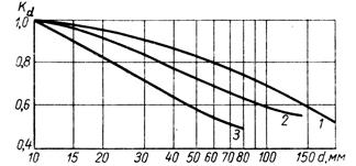 |
10.3.7. Determine factor Kd, that takes into account absolute dimensions of the shaft cross-section. For this purpose we use Fig.10.4.
|
Thus we have carbon steel without stress concentrators and Kd = 0.82.
10.3.8. Determine safety factors in terms of bending and torsion
 ;
;
 .
.
10.3.9. Determine the safety factor of the shaft at the critical section
 ;
;

Allowable values of the safety factor [ S ] are given in table 10.3.